


Entry posted by Knuckles
709 views
I had a pleasant supprise today to see I and a few others have been graciously published in the Scalefour News 180, even with a special URL made. I'm much honoured, 
Who do I thank?? :thumb
A mini update. I haven't wanted to post until I had something substantial to add so here is something marginly...substantial. Sub, more than Stantial...if that even makes sence. (Translation: There could have been more but I haven't done much modelling lately)
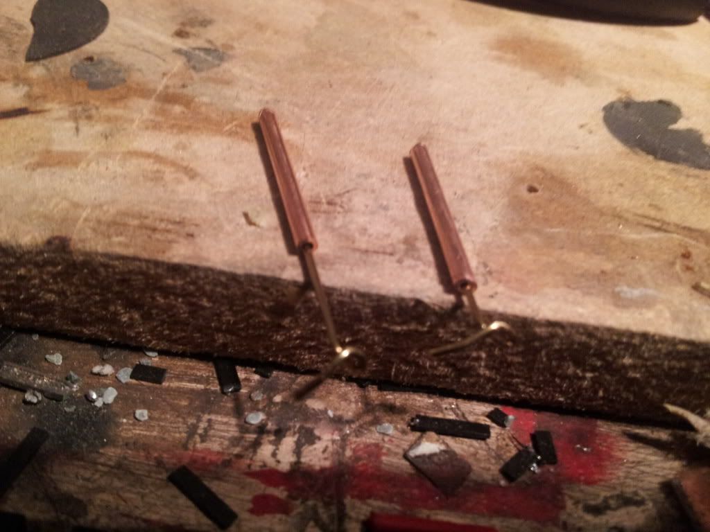
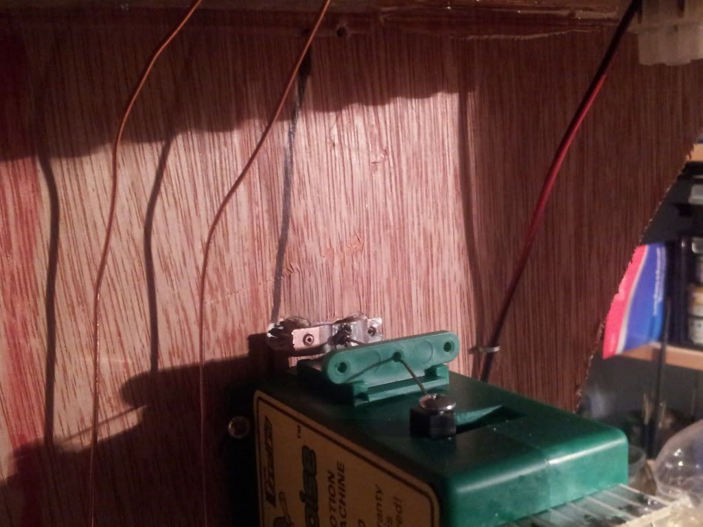
Finally submitting and taking the advice of using tubes for rigidity with flexibility (I insist on learning the hard way sometimes - you know for personal fact then) I have cobbled stretcherbar MKIII with copper tubes picked up from Warley, would have prefered brass as they solder better but I got what I could, the design is essentially the same but with the tubes added. I found that it helped a little but was still experiencing some of the problems I had previously. Whilst thinking of a way to retain the horizontal movement of the PCB stretcher bar without the twisting I devised a bodge that seems to have worked. I've seen some peoples methods of using thin wire rod and that may be better than what I tonight came up with, but as experimentation it seems to have worked nicely. Basically it's a 3rd tube for the pivot wire to go in; the pivot wire can still slide up and down but the virtical bracing prevents the PCB stretcher bar from rotating sideways too much as it almost 'locks' it in one plain, yet with plenty of wire play to prevent binding.
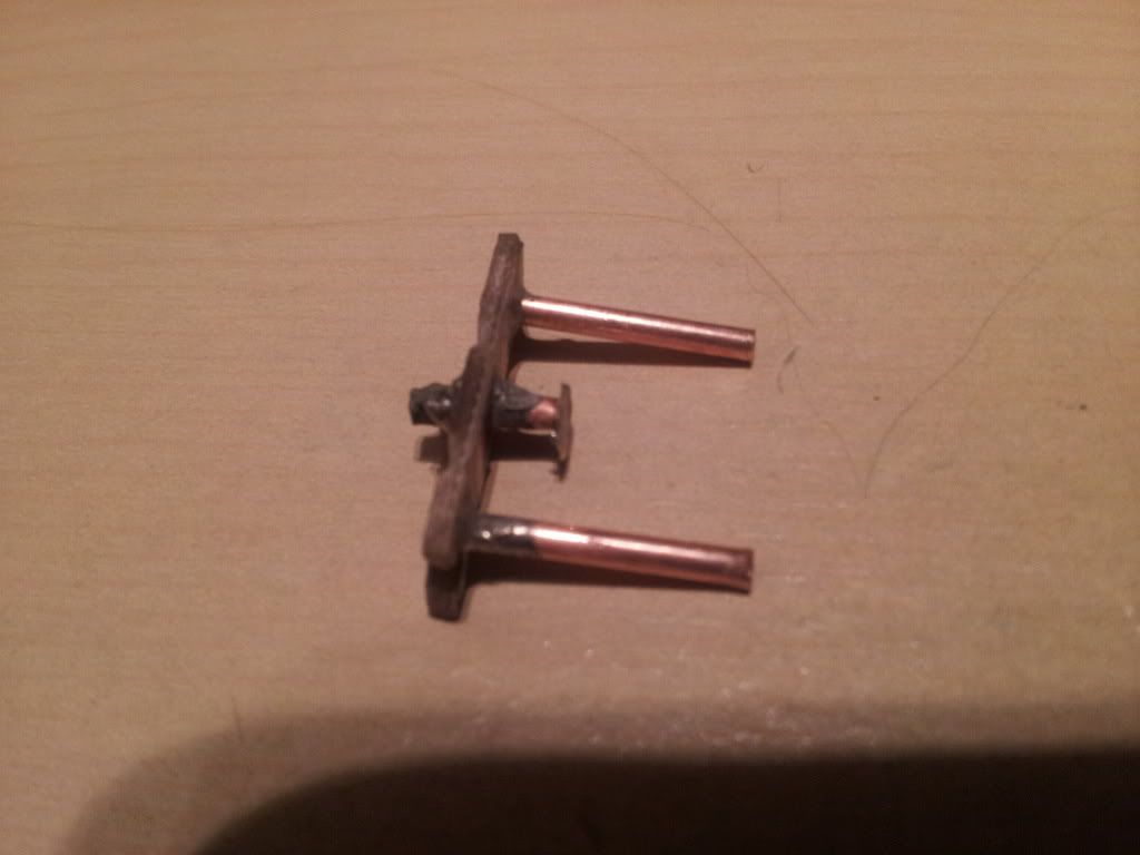
This is some of my dropper bars described in earlier posts in the tubes.
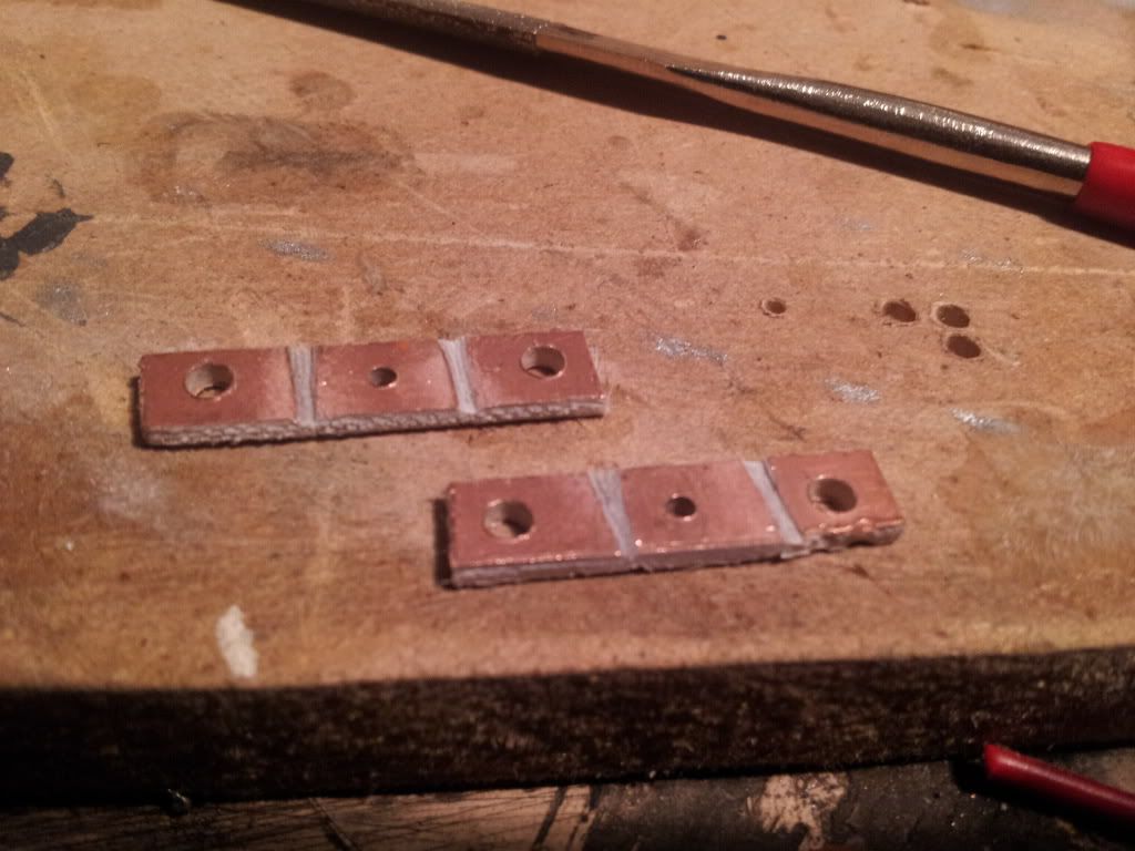
Some PCB stretcher bars with 4 electrical gaps in each. I only used one. Serious TIP: I have found repeatedly that even though I cut several insulation gaps to make sure, electricity insisted on somehow jumping accross. Using a multimeter I think is essential to ensure confidence here. I don't know weather it is copper filings or what but even after opening the gaps out and scrubbing with an old toothbrush it still seems to take a long time before they seems safe to use. Odd.
Tubes added.
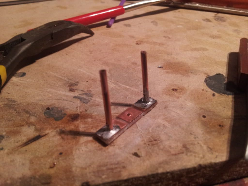
After some piddeling about I thought up this idea. 3rd tube as described in the text, then later I added a 'capping mushroom' as a due device to A stop the wire going to far and B provide a slight slide plate. Ideally it shouldn't touch the wood but I'd rather not risk things, bit of moistureising cream provided a lubricant! Weather it is suitable or not, or weather it will attract gunk and turn into a brake will be apparent once time has elapsed.
General impressions of the two turnout motors in place. Currently only wired for mechanical control as the rest will come later.
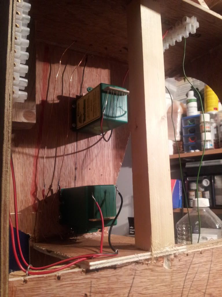
I had to cut out a teeny bit of the green adjustment slide to account for the PCB stretcher bar but I'm happy to do that. Avoids all the trouble of installing a wooden block anyway. Does in invalidate the wrarrenty? Erm? Possibly, I'm not bothered anyway.
That's it for now. Instillation of the 4th and last is going to be a challenge indeed because the point motor needs to go where the bridge will be and that's not going to happen. I'm thinking of possibly making some working overboard scale point rodding and angle cranks for operation. Am I mad and will I need a stiff whisky to accomplish it? Maybe another method is more sane and plausable.
-
 2
2

1 Comment
Recommended Comments
Create an account or sign in to comment
You need to be a member in order to leave a comment
Create an account
Sign up for a new account in our community. It's easy!
Register a new accountSign in
Already have an account? Sign in here.
Sign In Now